English
 عربى
عربى BLDC
BLDC

Content
- 1 What Aluminium Solar Rails Are and Why They Matter So Much
- 2 Aluminium Alloy Grades Used in Solar Rails and What They Mean for Strength
- 3 Common Aluminium Solar Rail Profile Types and Their Applications
- 4 Standard Dimensions and How to Choose the Right Rail Size
- 5 Surface Treatments for Aluminium Solar Rails: What Protects Them Long-Term
- 6 How to Calculate the Number of Aluminium Solar Rails You Need
- 7 Mounting Foot Spacing and Its Effect on Rail Performance
- 8 Thermal Expansion in Aluminium Solar Rails: Why It Matters and How to Manage It
- 9 Grounding and Bonding Requirements for Aluminium Solar Rails
- 10 How to Assess Quality When Comparing Aluminium Solar Rails from Different Suppliers
- 11 Installation Tips That Make Aluminium Solar Rail Systems More Reliable
What Aluminium Solar Rails Are and Why They Matter So Much
Aluminium solar rails are the extruded aluminium profile sections that form the structural backbone of virtually every roof-mounted solar panel system in the world. They run horizontally or vertically across a roof surface, spanning between mounting feet or brackets anchored to the roof structure, and provide the continuous support surface to which solar panel frames are clamped. Without properly engineered solar mounting rails, panels would have no secure, weather-resistant way to attach to a building — making the rail system as critical to a solar installation as the panels themselves.
The reason aluminium dominates solar rail manufacturing is not arbitrary. Aluminium combines a set of properties that are almost uniquely suited to outdoor structural applications: it is lightweight enough to minimise additional dead load on roofs, corrosion-resistant enough to last 25 years or more without protective coatings, strong enough in the right alloy grades to span meaningful distances between supports under wind and snow loads, and thermally conductive enough to handle the expansion and contraction cycles that outdoor temperature changes impose without fatigue cracking. It is also recyclable, which matters increasingly to solar project developers with sustainability requirements.
Aluminium solar mounting rails are available in a vast range of profile geometries, alloy grades, lengths, and surface treatments. Navigating this variety confidently — understanding which choices matter for performance and which are primarily cosmetic — is what separates a properly designed solar racking system from one that may fail prematurely or require costly remediation.
Aluminium Alloy Grades Used in Solar Rails and What They Mean for Strength
Not all aluminium is the same. The alloy grade of the aluminium used in solar rails directly determines their structural performance, corrosion resistance, and suitability for different installation environments. Most solar rail manufacturers specify their alloy grade in product datasheets, and this specification deserves attention when comparing products.
The most commonly used alloy grades in aluminium solar rail production are:
- 6063-T5 and 6063-T6: The most widely used alloy in residential and light commercial solar rail applications. 6063 is an aluminium-magnesium-silicon alloy specifically designed for extrusion — it flows well through complex die shapes, producing the precise, consistent cross-sections required for solar rail profiles. T5 and T6 refer to the temper condition; T6 (artificially aged after solution heat treatment) achieves higher yield strength than T5 and is preferred for longer rail spans and higher load applications. Typical yield strength for 6063-T6 is approximately 215 MPa.
- 6061-T6: A higher-strength alloy than 6063, with a yield strength of approximately 276 MPa. Used in commercial and utility-scale solar rail systems where longer spans between supports or higher wind and snow loads require greater structural performance. 6061 is slightly more difficult to extrude into complex profiles than 6063, so it is more often used in simpler cross-sections or for structural elements such as splice connectors and brackets rather than the main rail profile.
- 6005A-T6: A medium-strength alloy with better extrudability than 6061 but higher strength than standard 6063-T5. It is increasingly specified by European solar mounting manufacturers for systems requiring EN 755 compliance and is well-suited to the complex asymmetric profiles used in many contemporary solar rail designs.
For residential rooftop installations with standard rafter spacing and typical wind loads, 6063-T5 rails are adequate and widely used. For coastal environments, high-altitude locations with significant snow loads, or commercial installations with wide mounting foot spacings, specifying 6063-T6 or 6061-T6 provides meaningful additional structural margin. Always request the alloy and temper specification from suppliers — if a supplier cannot provide this information, treat the product with caution.
Common Aluminium Solar Rail Profile Types and Their Applications
The cross-sectional profile of an aluminium solar rail determines how it distributes load, how clamps attach to it, how it splices together between lengths, and how it manages thermal expansion. Several profile families dominate the solar industry, each with distinct characteristics.
Hat or Top-Hat Profile Rails
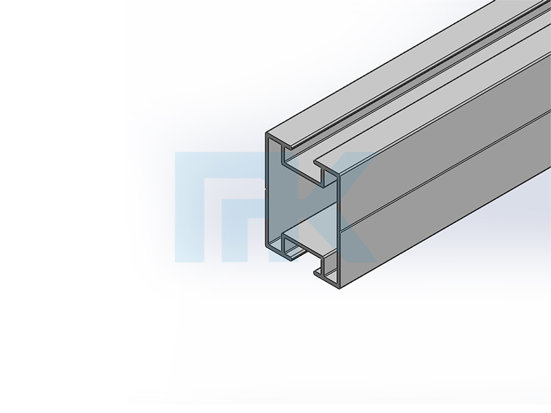
The hat profile is one of the most commonly used solar rail cross-sections globally. When viewed from the end, the profile resembles an inverted hat or top hat shape — a flat upper flange, two angled or vertical webs, and a wider lower flange. This geometry provides efficient bending strength relative to material weight, with the flanges carrying tension and compression loads and the webs providing shear resistance. The upper flange typically incorporates a T-slot channel that accepts the heads of T-bolts used for mid-clamps and end-clamps, enabling tool-free panel positioning along the rail. Hat-profile solar rails are used across residential, commercial, and ground-mount applications and are the default choice for most standard pitched roof installations.
C-Channel and U-Channel Profile Rails
C-channel and U-channel profiles have an open channel section oriented upward, providing a continuous slot into which clamp bolts can be positioned at any point along the rail without requiring pre-drilled holes. This makes panel spacing adjustment more flexible than some other profile types and simplifies installation on roofs where panel layout dimensions don't align perfectly with a fixed bolt-hole pattern. C-channel rails are commonly used in flush-mount ground systems and on flat or low-pitch roof applications. The trade-off is that open-channel profiles can accumulate debris, water, and bird nesting material more readily than closed profiles, which may require periodic cleaning in some environments.
Proprietary Integrated Profile Rails
Many major solar mounting system brands — including Schletter, K2 Systems, Renusol, and Unirac — produce proprietary extruded rail profiles that integrate specific features into the extrusion geometry: built-in grounding channels that contact the panel frame directly during clamping, integrated wire management channels, self-locking T-slot geometries that prevent bolt rotation during tightening, and asymmetric profiles optimised for one-sided module loading in east-west flat-roof applications. These proprietary rails are designed to work as a system with the manufacturer's own brackets, clamps, and accessories, providing tested and certified performance but typically at higher cost and with less component interchangeability than standard profile types.
Standard Dimensions and How to Choose the Right Rail Size
Aluminium solar rails are manufactured in standard cross-section dimensions that correspond to different structural capacity categories. Selecting the correct section size for a given installation involves matching the rail's section modulus to the bending loads imposed by panel weight, wind uplift, and snow accumulation over the support spacing used in the system.
| Rail Series | Typical Height × Width | Typical Application | Max Span (Indicative) |
| Light Duty (30–35 Series) | 35mm × 30mm | Small residential, carport canopies | Up to 900mm |
| Standard (40 Series) | 40mm × 40mm | Residential pitched roof, most common | Up to 1,200mm |
| Medium Duty (46–50 Series) | 46mm × 50mm | Commercial rooftop, higher snow/wind loads | Up to 1,500mm |
| Heavy Duty (68–72 Series) | 68mm × 40mm | Ground-mount, large commercial, high-load zones | Up to 2,000mm+ |
The span figures in the table above are indicative only — actual allowable spans depend on the specific alloy and temper, the applied load combination (dead load plus wind uplift or snow pressure), the panel clamping arrangement, and whether the rail is treated as a simply supported or continuous beam across multiple supports. For any installation where snow loads exceed 0.5 kN/m² or wind speeds at roof height exceed 130 km/h, a structural engineer should verify the rail selection and mounting foot spacing rather than relying solely on manufacturer span tables.
Surface Treatments for Aluminium Solar Rails: What Protects Them Long-Term
One of aluminium's most valuable properties is its natural formation of a thin, stable aluminium oxide layer that provides inherent corrosion protection — this is why bare aluminium performs far better outdoors than bare steel. However, for solar rail applications in aggressive environments, additional surface treatment significantly extends service life and preserves appearance over the system's 25+ year design life.
Mill Finish (Untreated)
Mill finish aluminium solar rails are supplied straight from the extrusion die without additional surface treatment beyond the natural oxide layer. This is the most economical option and performs adequately in most inland residential environments with moderate rainfall. However, mill finish aluminium is susceptible to surface oxidation that produces a white powdery patina over time, and in coastal or industrial environments the natural oxide layer alone is insufficient to prevent pitting corrosion from chloride or sulphur dioxide exposure. Mill finish rails should be avoided within approximately 1 km of coastlines or in industrial areas with elevated airborne pollutants.
Anodised Finish
Anodising is an electrochemical process that thickens the natural aluminium oxide layer to 10–25 microns, creating a hard, pore-sealed surface that is significantly more resistant to corrosion, abrasion, and UV degradation than mill finish. Anodised solar rails are specified in two main grades: AA10 (10-micron coating, suitable for inland environments) and AA20 or AA25 (20–25 micron coating, recommended for coastal and industrial environments). Anodised aluminium solar rails are the most widely specified finish for quality residential and commercial installations globally, offering an excellent balance of corrosion protection, service life, and cost. The anodised surface also provides electrical isolation at the rail surface, which is relevant in some system earthing configurations.
Polyester Powder Coat
Powder-coated aluminium solar rails are available in a range of colours — most commonly black, white, or RAL custom colours — making them preferable for applications where rail visibility is a design consideration, such as building-integrated PV (BIPV) applications, facade-mounted systems, or residential installations where the homeowner or planning authority has aesthetic requirements. Powder coat over a chromate conversion pre-treatment provides excellent corrosion protection, but the coating can chip or crack at mounting points during installation if not handled carefully, exposing bare aluminium beneath. Inspect powder-coated rails carefully after installation for any coating damage and apply a compatible touch-up primer to any bare areas before system commissioning.
How to Calculate the Number of Aluminium Solar Rails You Need
Correctly estimating rail quantity before ordering prevents the frustration and project delay caused by under-ordering, and avoids wasted material cost from over-ordering. The calculation is straightforward once you understand the layout logic.
- Determine the number of rail rows: For standard portrait-oriented solar panels on a pitched roof, two rail rows per column of panels is the most common arrangement — one rail near the top of the panel and one near the bottom, positioned within the manufacturer's specified clamp zone (typically 200–400mm from each short edge of the panel). Landscape orientation or very large panels may require three rail rows. Check the panel manufacturer's installation manual for their specified rail support positions.
- Calculate total rail length per row: Each rail row must span the full width of the panel array in that direction. Multiply the number of panel columns by the panel width (or height in landscape), adding 50–100mm overhang at each end of the array for end-clamp clearance. For example, a row of 5 panels each 1,134mm wide requires approximately 5 × 1,134mm + 200mm = 5,870mm of rail per row.
- Determine how standard rail lengths divide into your row length: Aluminium solar rails are typically supplied in 2.2m, 3.0m, 3.3m, 4.0m, 4.2m, and 6.0m standard lengths. Minimising offcuts means selecting a standard length that divides well into your row length with minimal waste. Spliced joints between rail sections must be positioned over a mounting foot location — not in mid-span — so plan splice positions accordingly.
- Multiply by number of rows and add a cutting allowance: Total rail length = number of rows × total row length × 1.05 (adding a 5% allowance for cutting waste, damaged ends, and on-site adjustments). Convert to the number of standard-length pieces required, always rounding up.
- Account for separate east-west or tilt-frame arrays separately: If the installation includes multiple separate arrays at different orientations or on different roof planes, calculate each sub-array independently and sum the totals. It is common for installers to need different rail lengths for different roof sections on the same building.
Mounting Foot Spacing and Its Effect on Rail Performance
The spacing between mounting feet — the points at which the rail is supported by brackets anchored to the roof structure — is the single most important variable affecting the structural performance of an aluminium solar rail system. All other rail specifications (alloy, profile size, surface treatment) assume a specific maximum support spacing to achieve their rated load capacity.
In practice, mounting foot spacing is largely dictated by the spacing of the structural members to which the feet must anchor — rafters in a timber-framed roof, purlins in a steel building, or structural slabs and beams in a flat-roof installation. This creates a fundamental tension in system design: the ideal structural spacing for the rail may not align with the available structural fixing points in the building.
For pitched timber rooftop installations, rafter spacing is typically 400mm, 600mm, or 900mm depending on the building age and construction standard. A 600mm rafter spacing allows mounting feet to be fixed at every rafter (600mm spacing) or every second rafter (1,200mm spacing). The standard 40-series solar rail in 6063-T6 typically has a rated span of 1,200–1,400mm for typical residential load cases — meaning every-second-rafter fixing is usually structurally adequate for most residential wind and snow load conditions.
Where rafter spacing forces mounting foot spacings that exceed the rail's rated span, there are three options: upgrade to a heavier-duty rail section with higher structural capacity; install additional intermediate supports using specialised spanning brackets; or redesign the layout to reduce the effective span. Each option has cost and installation complexity implications that should be evaluated against the structural requirement before ordering materials.
Thermal Expansion in Aluminium Solar Rails: Why It Matters and How to Manage It
Aluminium has a coefficient of thermal expansion of approximately 23 × 10⁻⁶ per degree Celsius — meaning a one-metre length of aluminium rail expands or contracts by 0.023mm for every 1°C change in temperature. Over the temperature range that rooftop solar equipment experiences in most climates — perhaps -10°C in winter to +70°C on a hot summer roof surface — this equates to a total movement of about 1.8mm per metre of rail length.
For a single 2.2m rail section, this movement is approximately 4mm over the full temperature range — manageable. But for a continuous spliced rail run extending 10–12 metres across a large commercial rooftop, the same calculation produces 18–22mm of total thermal movement. If this movement is constrained by fixed connections at both ends of the rail run, the resulting compressive or tensile stress in the aluminium can cause buckling, distortion of panel clamp positions, or fatigue at splice connector points.
The standard engineering solution is to designate one mounting foot per rail run as a fixed point (using a lock washer or fixed bracket that prevents rail sliding) and allow all other mounting feet to act as sliding supports that permit longitudinal rail movement. Rail splice connectors between adjacent rail sections should also be designed to accommodate movement — sliding rather than rigidly fixed splices are preferable for long rail runs. Most quality solar mounting system manufacturers specify which mounting feet should be fixed and which should be sliding in their installation documentation, and this instruction should be followed precisely.
Grounding and Bonding Requirements for Aluminium Solar Rails
Electrical grounding and bonding of aluminium solar rails is a code requirement in most jurisdictions and a critical safety element of any PV system. The rail system provides the metallic pathway by which panel frames, mounting hardware, and the array structure are bonded together and connected to the system's grounding electrode. Getting this wrong creates shock hazard and may void system warranties or fail electrical inspection.
- Understand the difference between grounding and bonding: Bonding connects all metal components of the array structure together to ensure they are at the same electrical potential, eliminating the risk of shock from touching two metallic components at different potentials. Grounding connects the bonded system to earth. Both are required, and the rail system is a primary component of both.
- Anodised rails require special bonding attention: The anodised layer on anodised aluminium solar rails is an electrical insulator. Panel clamps, mid-clamps, and rail splice connectors that rely on metal-to-metal contact for bonding continuity must penetrate or bypass the anodised layer. Many modern clamps incorporate stainless steel serrations or biting teeth that penetrate the anodise during tightening, establishing a conductive connection. Verify that the clamps specified for your system are rated as bonding clamps if you are relying on clamp contact for bonding continuity.
- Use dedicated grounding lugs where required: In systems using anodised rails where clamp-based bonding continuity cannot be confirmed, dedicated grounding lugs — stainless steel connectors that mechanically bite through the anodised layer and accept a grounding conductor — should be installed at the rail, connected with appropriately sized copper bonding wire to adjacent rails and the system grounding point.
- Avoid aluminium-copper direct contact at grounding connections: Direct contact between aluminium and copper conductors in the presence of moisture causes galvanic corrosion of the aluminium, which progressively increases contact resistance and may eventually destroy the grounding connection. Use bi-metallic lug connectors rated for aluminium-to-copper connections, or a tin-plated copper lug at the aluminium connection point.
- Follow local electrical code requirements: Grounding requirements for solar rail systems vary between jurisdictions. NEC 2017 and later editions in the United States, AS/NZS 5033 in Australia and New Zealand, and IEC 60364-7-712 in European jurisdictions each have specific requirements for PV array bonding and grounding conductor sizing. Always verify the applicable code edition and local amendments before finalising grounding design.
How to Assess Quality When Comparing Aluminium Solar Rails from Different Suppliers
The global aluminium solar rail market includes products from established European and North American manufacturers with decades of testing and certification behind their products, as well as a large volume of lower-cost products from manufacturers where quality control is inconsistent. Knowing how to evaluate quality before purchasing — beyond simply comparing price per metre — protects the long-term performance of the entire solar system.
Check for Third-Party Structural Certification
Quality solar rail manufacturers provide structural load tables backed by third-party engineering certification — typically from a licensed structural engineer or a recognised testing laboratory. These tables specify the maximum allowable spans and loads for each rail profile under defined load conditions. Rail products sold without structural load data should not be used in any installation where structural performance is a safety consideration — which is every rooftop installation. In some jurisdictions, uncertified rail products will fail building permit or electrical inspection regardless of how they perform in practice.
Request Mill Certificates for Alloy Verification
A material test certificate (mill certificate) from the aluminium extrusion supplier documents the actual alloy composition and mechanical properties (yield strength, tensile strength, elongation) of each production batch of rail material. Reputable manufacturers can provide these certificates on request. If a supplier is unable or unwilling to provide mill certificates, there is no reliable way to verify that the alloy grade claimed on the product label corresponds to the actual material — a meaningful concern given that substituting lower-grade alloy reduces structural capacity without any visible indication.
Inspect Profile Dimensional Consistency
Measure cross-section dimensions of received rails against the manufacturer's published drawings, and check wall thickness at multiple points along the length. Consistent, accurate dimensions are a direct indicator of extrusion quality and die maintenance standards. Rails with variable wall thickness, surface waviness, or dimensional deviations beyond ±0.5mm should be rejected — dimensional inconsistency affects both structural performance and clamp engagement reliability. T-slot dimensions in particular must be precisely maintained for clamp heads to engage correctly without excessive play or binding.
Installation Tips That Make Aluminium Solar Rail Systems More Reliable
The quality of installation has as much impact on long-term system performance as the quality of the rails themselves. These practical installation considerations address the most common sources of problems in aluminium solar rail systems.
- Cut rails cleanly with appropriate tools: Use an aluminium-specific circular saw blade (high tooth count, negative rake angle) or a mitre saw with a fine-tooth blade for cross-cuts. A clean, square cut is essential for splice connector fit and for preventing burrs that can damage anodised finishes on adjacent components. Deburr cut ends with a file or deburring tool before assembly. Never cut aluminium rails with an angle grinder — the heat generated can locally soften the aluminium and the rough cut creates sharp burrs that are a handling hazard.
- Use anti-seize compound on stainless steel fasteners into aluminium: Stainless steel fasteners — the correct choice for aluminium rail systems due to galvanic compatibility — can gall and seize in aluminium threads if tightened without lubrication. Apply a small amount of anti-seize compound (nickel-based or copper-based) to the threads of stainless bolts before installation in aluminium nuts or tapped holes. This also makes future disassembly possible without damage to the aluminium thread.
- Install rails parallel and at consistent height before mounting panels: Use a spirit level and chalk line to ensure all rail rows are parallel to each other and at the correct height relative to the roof surface. Misaligned rails cause panel frame distortion when clamped, which stresses the panel frame, may crack the glass near clamp points, and voids most panel manufacturer warranties. Take time at the rail installation stage — it is far faster to adjust rails before panels arrive on the roof.
- Torque fasteners to specification with a calibrated torque wrench: Under-torqued clamp bolts allow panels to shift under wind loading, causing fretting damage to panel frames and rail surfaces. Over-torqued bolts can crack panel frame corners or strip aluminium threads. Use a calibrated torque wrench set to the manufacturer's specified torque value — typically 10–15 Nm for M6 mid-clamp bolts and 15–25 Nm for M8 end-clamp and mounting foot bolts. Record the torque specification used for the installation records and warranty documentation.
- Route and secure DC wiring before panels are fully installed: Once panels are clamped in place, access to the rail channel and the underside of the array for wire routing is severely restricted. Plan the wiring route, install any wire management clips or channel inserts in the rail T-slot, and route the DC home runs through the system before the final row of panels is installed. This prevents wire sag onto the roof surface, reduces UV degradation of cable insulation, and presents a safer and more inspectable installation.